Monday, March 3, 2014

Project you are the ONE. a Wireless powered fiber optic side glow diffused bling

Project you are the ONE. a Wireless powered fiber optic side glow diffused bling
When I was kid, I was fascinated by the world where Tesla and Edison live in. What intrigued me most was the constant debate of AC and DC (at that time), and Tesla’s vision of having power transmitted wirelessly. No cables necessary, no copper mined unnecessarily and friendly to all humans. Wireless power transfers (inductive charging) at that time are pretty much far fetch idea. Nonetheless, the man himself went tirelessly (and possibly drove penniless) to prove his “thing”. Tesla’s destitute demise contrary to Edison’s prosperous life strikes me really hard. I nearly gave up on the dreams to study engineering; thinking I should be a business man or middle man making the in-between of deals.
While growing up, I did get my stab at making a wireless power transfer kit; reading up various recipes from various sources such as text books, “cook books” from BBS etc. , proving the materials read. At that time, I can’t even differentiate the difference between a normal copper wire and enameled wire. Both look the same to me. Without a master to guide in the field of making wireless power transfer (inductive charging) works; many failures afterwards, I came to a conclusion that probably I am better off hitched to my computer (intel 486).
Recently, while doing some read up on “Qi” the inductive power (wireless charging) standard for smartphones, suddenly I realized this might be the perfect time where the inductive charging technology has matured for end users like me to toy on the idea.
I have this idea of making novelty jewelry for the missus: wearable electronics of some sort with wireless power transfer aka inductive charging. The concept story board goes this way: At a seeming random event, I would have a little girl present her with a nicely decorated box that contains the novelty jewelry I made, with a message asking her to “follow the rabbit”. Hopefully the design of the jewelry would be very tempting such that she would put on straight away. Then a rabbit inspired character would walk pass her and hopefully, she would pick up the subtle message of following the rabbit. While following the rabbit, she will come across a few interesting characters that are staged, and the last character to appear will be me. Naturally, we would reach out to each other. Me, being the techie would have the transmitter end of inductive charging well hidden in my hand, and hook up to a ubiquitous disguised mobile power supply that supplies 12V, 1A.
Out of sudden (it is just a matter of time/distance for the EM fields to resonates between the tx loop and the rx loop), her novelty jewelry will light up and the light intensity grew greater as we are moving closer to touch! YESS! You are the one! Both of us will proclaimed. That’s the perfect time for me to take a knee, standby with a unique marriage proposal ring. 

What else? Propose to her!! this engineered piece of art definitely will work. Trust me, I am an engineer.
Oh waittttttttttttttttttttttttttttttttt…………I don’t have a missus/wife/GF yet.
This instructables assumes the following parts.
1x wireless charging kit. I got one set that is Chinese made at 13USD from aliexpress.
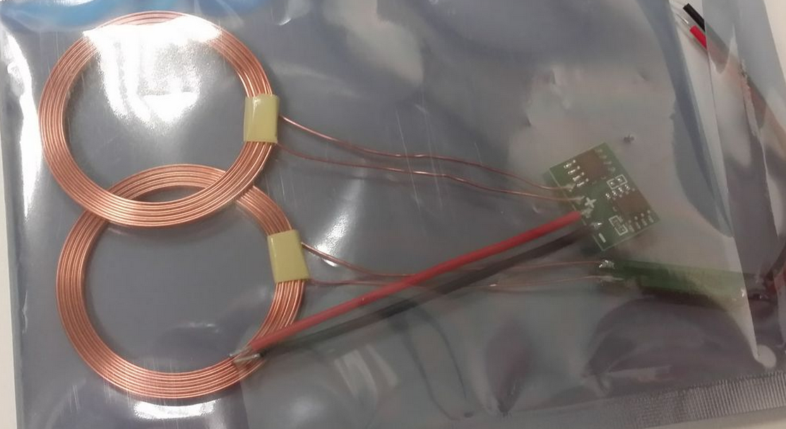
1x apparatus with RGB LED fading PCB of some sort, which consist of a microcontroller such as Arduino or ATTiny85, a RGB LED and a custom PCB or veroboard. A tutorial to program ATTiny85 with Arduino is available and the necessary ATTiny ISP shield can be made too.
There are many derivatives floating on the Internet. I have used my own recipe of ATTiny85 with RGB. The
step by step guide of “cooking” a PCB of your own is available here.
1x 5mm side glow fiber optic sufficient to cover the perimeter of the wearable apparatus of choice.
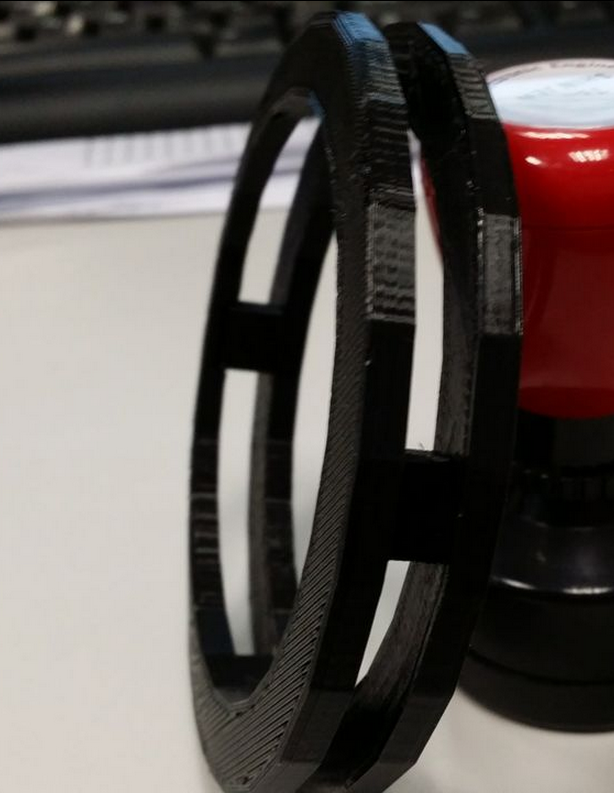
1x 3D printed custom made jewellery to hold the electronics, rx loop, and fiber optic. I have chosen to use a 3D printed bangle. The STL is available here. Print it twice. The two halves are snap fit. It was done in sketchup with the help from xinteng a DCPE yr1.
Step1: Assemble the RGB fading PCB, program the ATtiny 85 and mount it onto the PCB. Fiber optic cable is then inserted into a 5mm heat shrink tube. The contraption is then inserted to the 5mm RGB led.
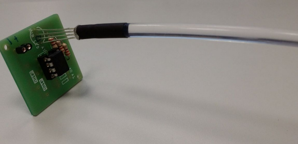
Step2: the assembled contraption in the earlier step is then assembled with the 3D printed bangle. The fiber optic cable are is elastic, and should not be bent at sharp angles. It keep slipping out of the 5mm gap designed to hold it, so I have to resort to cable ties to hold them in place.
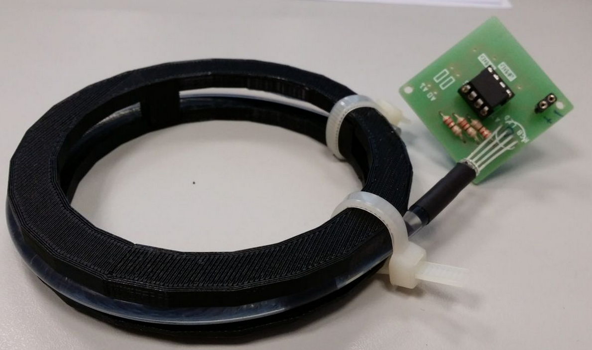
Step3: Test the contraption with 3V battery to test for functionality
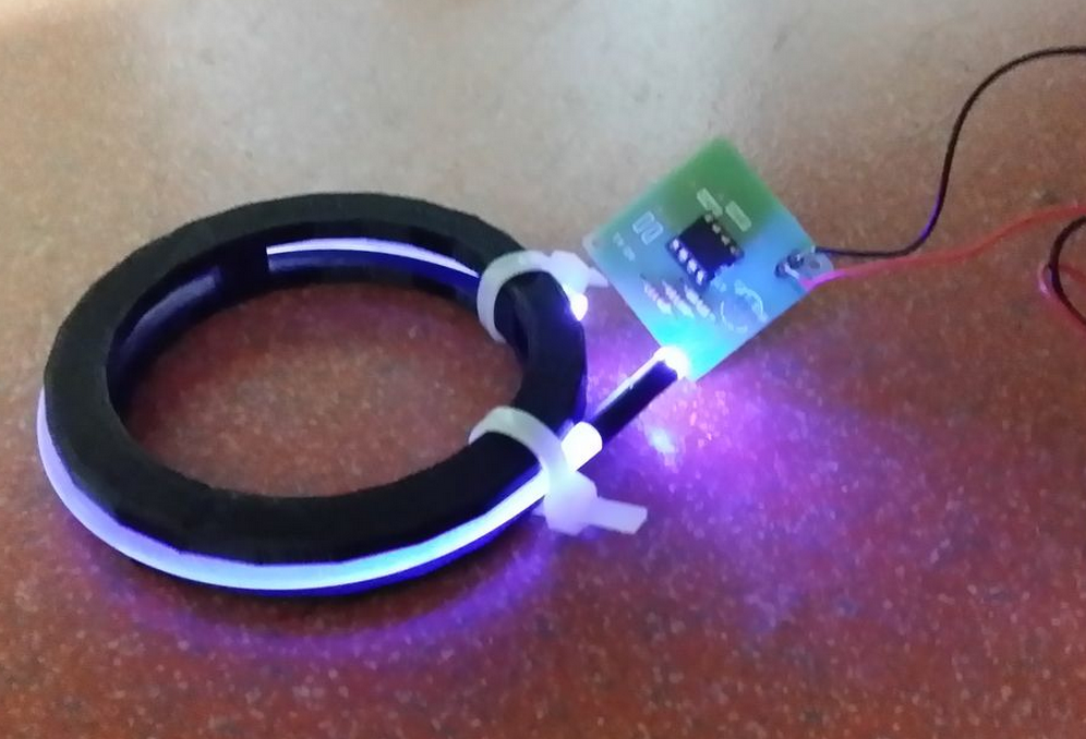
Step4: Assemble the contraption with the RX induction coil and PCB. I have to resort to use some masking tape to keep the wires in place.
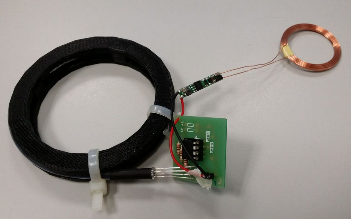
Step5: Test the contraption with TX loop connected to DC power supply. The power supply is set to 12V, 1A.
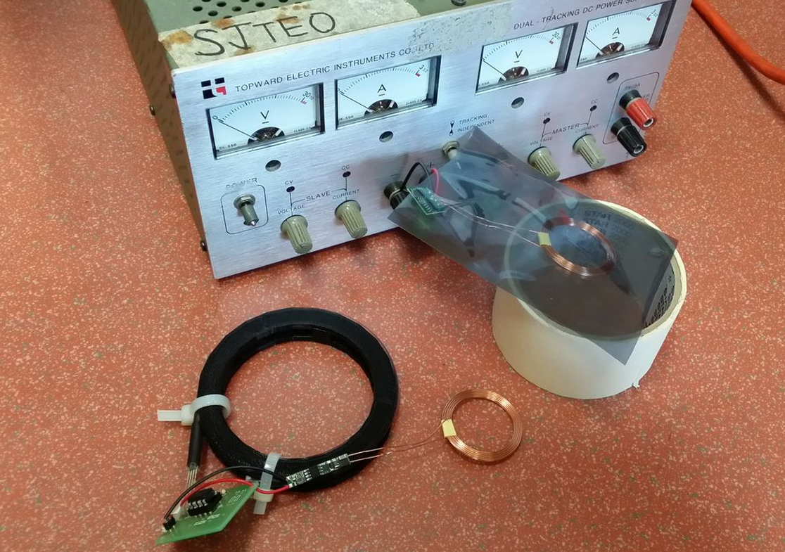
Step5: final check before turning on the DC supply. After turning on the DC supply, observe the behaviour on the EM fields w.r.t to the tx and rx loop. Note: No wireless transfer if the rx and tx loop are orthogonal to each other. The EM fields just cancel each other off.


Look! No batteries needed!

Closeup
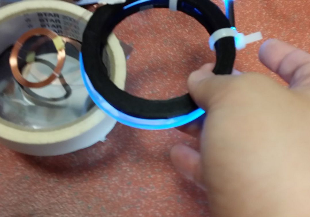
here comes the video

Saturday, March 1, 2014

Fujitsu E8410 laptop LCD panel LT154P3-L02 with LCD controller A.VST29.01

Fujitsu E8410 laptop LCD panel LT154P3-L02 with LCD controller A.VST29.01
Couple of weeks back I gave my well-deserved Fujitsu E8410 laptop a break, with it broken down into parts level. The LCD controller A.VST29.01 I ordered arrived early last week. It is Chinese made, and I can even find a data sheet for it on the Internet. With proper documentations, gone are the days we have to make some educated guesswork on unknown PCB. The price is USD29.9 without the AC adapter (12V, 4A); USD 51 for the complete set.
My schedule is still as hectic as hell, at the office and during office hours I am distracted with human presence, spent most of the time solving other human’s problem. Only at the weekends in the dead silence of my office, I am highly productive. In this precious undisturbed time I get things done.
In the comment post some ask why I would take all the trouble to fix instead of buying new laptop. 99% time these are the trolls that are trying to promote their business on blogs that allow for comment.  My answer: Re-purposing old electronics will reduce human’s dependency on Mother Nature’s generosity. 
The boom in electronics driven by capitalistic consumerism has humans scrambling to mine lithium to be used in rechargeable batteries, fossil fuels, precious metals to be used in producing electronics circuit boards and more. It is just a matter of when natural resources will be depleted, and I am dead sure I will not survive to see discarded electronics in the landfill takes it natural cause to be turned into resources again. Prolonging the EOL of electronic products by repurposing into other usage should reduce electronic waste. Some might argue that using another piece of electronics to prolong EOL (End Of Life) is also capitalistic consumerism and driving consumption. True, but to a certain extend. I do not have the exact quantitative data to retort this rhetorical statement. Nonetheless, qualitatively, if 100 units of resources are used to manufacture a laptop and deliver it to end user, contrasting it with 10 units of resources are used to manufacture an electronic circuit and delivered to end user to prolong it; the projected 90 units of unconsumed resources would stay unmolested in the sacred earth reserves.
Major manufacturing house would love to silence disapproving voices like mine that might hurt their profit base line by not consuming/buying new stuff. The power is to the people with a choice, liberated with domain knowledge shared by inhabitants on the Internet. We are not alone.
Let the transmission of how-to begin.
The package comes in 3 PCBs. The largest piece is the LCD controller, the larger rectangle shape PCB is the Inverter, it’s purpose is to power up the LCD panel’s backlight. Warning: the inverter contains high voltage during operation. Even it is disconnected from the supply, ensue safety precautions such as disconnecting from the mains, wear rubber sole shoes, not touching any bare metal area (soldering on the PCB are exposed to touch) are taken before handling the inverter PCB. There is a clear plastic surrounding the inverter. That is not meant for decoration, but prevents accidental in contact with the exposed area. DO NOT REMOVE THIS PLASTIC COVER! The smaller rectangle PCB is the panel where there are push button switches to control OSM (On Screen Menu).
The how-to is simple. Merely dismantle the LCD panel to the bare component level, remove the original LVDS cable and replace it with the one that comes with the LCD Controller. Some are weary of carelessness of flipping the connector and make a blunder out of it. No fret! The LVDS connector only goes in one direction, due to the design of it as depicted in the picture below from the LCD controller. Well, forcing the reversed connector definitely will damage the LCD panel and LVDS connector. The LVDS connector is replaceable, but not the receiving side on the LCD panel.
The following diagrams depict the original cable in 3 states. “A” is written to depict the direction and also the orientation of the connector. Just my handy way of labelling things I am opening up for the first time and ensuring I can put it back as per the original state later.
After assembling the LVDS cable, this is how it is look like.
The bird-eyes view of the connection.
Circle in red is where the LCD panel’s back lamp is connected to the inverter. Square in red is the LCD controller’s LVDS cable connecting to the LCD panel. Some scotch tape is used to secure the wiring at a convenient location.
The E8410 laptop boasts a magnesium alloy casing on the LCD (that’s the reason I choose the model!!), and it is difficult to cut through metal with my bare minimal tools. So I have made an inconspicuous  incision at the plastic area of the front cover to allow wiring to pass.
A final check before turning it on! This step is very crucial! Do not skip the final check before turning on!!!
Turning it on, and familiarising with the OSM.
Connecting it to the vga of my gaming rig (i7, 8GB ram, 128GB SSD, GTX 550Ti, win7x64), it works at 1280x720. One short note, I connected it to the VGA of my office laptop (i7, 500GB,8GB ram, win7x32{I know, this is a piece of joke. Stop making fun of it}) prior to my gaming rig. I have tried a myriad of resolution from 640x480 to 1280x720. Unfortunately, office laptop decides not to co-operate. Luckily I have my gaming rig in my office to offer a second opinion. Otherwise, I would have to hastily conclude my weekend project in my office a failure. Oh, did I mention that my gaming rig is in my office???!!

This weekend is the IT show in Singapore and I am such a cheapskate to spent very little $$. LOLx